
Device Configuration With Packet Tracer
Right, so this is the first lab in the CCNA Packet Tracer series and we’re kicking things off with the absolute basics. Hostnames, passwords, getting interfaces up – the stuff you need sorted before anything else makes sense.
Now look, I know what you’re thinking. Basic device configuration? Bit boring isn’t it? But here’s the thing – if you can’t navigate the CLI properly and you don’t understand which mode you’re in, you’re going to struggle with everything that comes after. I’ve seen people waste hours trying to run commands in the wrong mode, wondering why nothing’s working. So we’re going to get this nailed down properly from the start.
Grab the Packet Tracer file and lab guide from the GitHub repo: https://github.com/learn-skillnuggets/CCNA-Packet-Tracer

The Topology We’re Working With
Nothing complicated here. Two routers, two switches, four PCs. R1 and R2 are connected via a point-to-point link using a /30 subnet – that’s 10.0.0.0/30 if you’re following along. Each router has a LAN segment behind it with a switch and a couple of PCs.
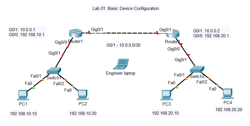
R1’s LAN is 192.168.10.0/24. R2’s LAN is 192.168.20.0/24. The whole point of the lab is to get these two networks talking to each other, which means configuring the interfaces, setting up static routes, and making sure everything’s actually working by the end.
The PDF topology diagram is in the GitHub repo if you want to print it out or have it on a second screen while you’re working. I find it helpful to have the diagram visible so I’m not constantly trying to remember which IP goes where.
Understanding the CLI Modes
This is where a lot of people come unstuck early on. Cisco’s CLI has different modes, and the commands available to you change depending on which mode you’re in. Try to run a configuration command from the wrong mode and it’ll just throw an error at you.
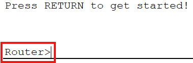
When you first connect to a device via console, you land in User EXEC mode. You’ll see the hostname followed by a greater-than symbol – something like Router>. There’s not a lot you can do here to be honest. You can run some basic pings, check a few things, but you can’t see the running configuration and you definitely can’t change anything.
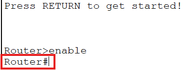
Type enable and you move into Privileged EXEC mode. The prompt changes to a hash symbol – Router#. Now you’ve got access to all the show commands. You can look at the running config, check interface status, view the routing table – all the diagnostic stuff. But you still can’t actually configure anything.
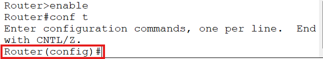
To make changes, you need to get into Global Configuration mode. Type configure terminal – or just conf t if you want to save yourself some keystrokes – and the prompt changes to Router(config)#. This is where the real work happens. Hostnames, passwords, routing protocols, all of that gets configured from here or from sub-modes underneath it.
And that’s the thing – there are sub-modes as well. If you want to configure a specific interface, you drop into Interface Configuration mode with something like interface GigabitEthernet0/0. The prompt changes again to Router(config-if)# so you always know where you are. Same idea for line configuration when you’re setting up console or VTY passwords – line console 0 drops you into Router(config-line)#.
The end command takes you straight back to Privileged EXEC mode from anywhere in the configuration hierarchy. Dead useful when you’ve finished configuring something and want to run a show command to verify it worked.
I go through all of this in the video, showing you what happens at each level and how the prompt changes. Once you’ve seen it a few times it becomes second nature, but it’s worth understanding properly rather than just memorising commands.
What We’re Actually Configuring in Packet Tracer
Let me walk you through what the lab covers. The video demonstrates the full configuration on R1 and SW1, then you’ll apply the same process to R2 and SW2 using the lab guide.
Hostnames and Banners
First thing we do is set the hostname. Simple enough – hostname R1 from Global Configuration mode. You’ll see the prompt change immediately from Router(config)# to R1(config)#. Makes it much easier to know which device you’re actually on, especially when you’ve got multiple terminal windows open.
Then we configure a message-of-the-day banner. In a real environment this would be your legal warning about unauthorised access – something the lawyers insist on. The command is banner motd followed by a delimiter character and your message. Whatever character you use to start the banner, you use the same one to end it.
Passwords – Getting This Right
Now this is important. There are different types of passwords on Cisco devices and you need to understand which ones to use.
The enable secret is what protects access to Privileged EXEC mode. When someone types enable, this is the password they need to enter. Always use enable secret rather than enable password. The secret version uses MD5 hashing – proper encryption that can’t be easily reversed. The password version uses Type 7 encryption which is absolute rubbish. Anyone can decode a Type 7 password in seconds with tools freely available online. So enable secret class it is – and yes, we’re using “class” as the password because this is a lab environment. Don’t use that in production obviously.
Console passwords protect the console port – the physical connection you’d make with a laptop and a console cable. We configure this under line console 0. Set a password with password cisco, then enable it with login. The login command is what actually tells the device to prompt for the password. Forget that and anyone can connect to the console without authentication.
While we’re in there, I also configure logging synchronous. This stops console messages from interrupting your typing. Without it, syslog messages pop up in the middle of whatever you’re typing and it gets really annoying really quickly. Doesn’t affect functionality but makes your life much easier.
VTY lines are for remote access – Telnet and SSH connections. Same idea as the console – set a password and enable login. VTY lines 0 through 4 give you five simultaneous remote sessions, which is plenty for most scenarios.
Interface Configuration
Router interfaces are administratively down by default. This catches people out all the time. You configure your IP address, everything looks fine, then you wonder why there’s no connectivity. It’s because you forgot no shutdown.
For each interface we’re configuring an IP address, adding a description, and bringing it up with no shutdown. The description doesn’t affect anything technically but it’s good practice – when you come back to this device in six months you’ll thank yourself for documenting what each interface connects to.
On R1, GigabitEthernet0/0 gets 192.168.10.1/24 – that’s the LAN side connecting to SW1. GigabitEthernet0/1 gets 10.0.0.1/30 – that’s the WAN link to R2. Same logic on R2 but with the appropriate addresses for that side.
One thing to note – these are 2911 routers so the interfaces are GigabitEthernet, not FastEthernet. G0/0, G0/1, G0/2. If you’re coming from older equipment or different Packet Tracer topologies, make sure you’re using the right interface names.
Static Routes
With the interfaces configured, each router can reach its directly connected networks but doesn’t know how to get to the other side. R1 knows about 192.168.10.0/24 and 10.0.0.0/30 because those are directly connected. But it has no idea that 192.168.20.0/24 exists on the other side of R2.
So we add a static route. On R1: ip route 192.168.20.0 255.255.255.0 10.0.0.2. This tells R1 that to reach the 192.168.20.0/24 network, send traffic to 10.0.0.2 – which is R2’s interface on the point-to-point link.
Same thing on R2 but pointing back the other way: ip route 192.168.10.0 255.255.255.0 10.0.0.1.
With those routes in place, traffic can flow between the two LAN segments. We verify this works by pinging across the network and checking the routing table with show ip route.
Switch Configuration
The switches need configuring too. Hostname, enable secret, console and VTY passwords – same as the routers. But switches also need a management IP address if you want to access them remotely.
On a Layer 2 switch, you configure the IP address on VLAN 1 – the default VLAN. It’s not a physical interface, it’s a logical interface. interface vlan 1, assign the IP address, and don’t forget no shutdown. Switches also need a default gateway configured so they know where to send traffic destined for other networks – ip default-gateway 192.168.10.1 in Global Configuration mode.
Verification – Making Sure It Actually Works
No point configuring everything if you don’t verify it’s working properly. The lab guide has a full list of verification commands but the main ones are:
show ip interface brief gives you a quick overview of all interfaces, their IP addresses, and their status. You want to see “up” and “up” in the Status and Protocol columns. If you see “administratively down” you’ve forgotten the no shutdown command.
show running-config shows you exactly what’s configured on the device. Scroll through and check your hostnames, passwords, interface configurations, routes – everything should be there.
show ip route displays the routing table. You’ll see your directly connected networks marked with a C and your static routes marked with an S. If the static route isn’t there, something’s wrong with how you configured it.
Then test actual connectivity. Ping from R1 to R2’s interfaces. Ping from R1 to the PCs on R2’s LAN. Ping from PC1 all the way across to PC3 and PC4. If all those pings succeed, you’ve got end-to-end connectivity and the lab is complete.
Finally, test your VTY configuration by telnetting from R1 to R2. You should be prompted for the VTY password. If you get in, your remote access is working.
Common Mistakes I See All The Time
Forgetting no shutdown on router interfaces. I mentioned it already but it’s worth repeating because it catches so many people out. Configure the IP address, looks fine, nothing works. Check the interface status – administratively down. Add no shutdown, suddenly everything’s working.
Using the wrong interface names. These are 2911 routers with GigabitEthernet interfaces. If you’re typing interface FastEthernet0/0 it’s not going to work because that interface doesn’t exist on this router.
Forgetting to save the configuration. Everything you configure goes into the running-config, which lives in RAM. Reboot the device and it’s gone. write memory or copy running-config startup-config saves it to NVRAM so it survives a reboot. Get into the habit of saving regularly.
Using enable password instead of enable secret. I covered this earlier but it’s a common mistake. The password version is insecure. Always use secret.
Not setting the default gateway on switches. The switch will work fine for forwarding traffic between devices, but you won’t be able to manage it remotely from a different subnet because it doesn’t know how to send return traffic back to you.
In the video I make a couple of mistakes myself and have to go back and fix them. I didn’t follow the instructions properly at one point and missed configuring the console password on one of the switches. These things happen – the important thing is checking your work with show commands and fixing what needs fixing.
CCNA 200-301 Exam Topics Covered
This Packet Tracer lab maps to the following exam objectives:
1.1 – Explain the role and function of network components Understanding what routers and switches do, how they connect, what the different interfaces are for.
5.3 – Configure device access control using local passwords Enable secrets, console passwords, VTY passwords – all the basic device hardening we covered.
What’s Next
Once you’ve got this lab working, you’ve got the foundation for everything else in the series. You understand the CLI modes, you can configure basic settings, you know how to verify your work.
Lab 02 builds on this with more detailed IPv4 addressing and subnetting practice. We start looking at different subnet sizes, understanding CIDR notation, and working with more complex topologies.
But don’t rush ahead. Make sure you can complete this lab confidently. Configure R2 and SW2 yourself using the lab guide. If you get stuck, rewatch the video. The point is to get comfortable with the process so it becomes second nature.
Right, that’s Lab 01 done. Get it configured, verify your connectivity, and I’ll see you in the next one.
Cheers, Dickie